Workshop Resources: Introduction to Electronics
This webpage has been designed to support our in-person Introduction to Electronics Workshop.
Each group should have:
- BBC Micro:Bit
- Breakout board
- Battery bank
- USB to micro USB data cable
- A randomly selected numbered component
You will then need to open a new project on Makecode for programming your Micro:Bit.
Task 1: To identify and successfully program your numbered component.
Task 2: Create a programmed circuit using both an input and output device.
For information to help wire, program and identify your component, select the relevant button (same number as your random component) below.
Component 1
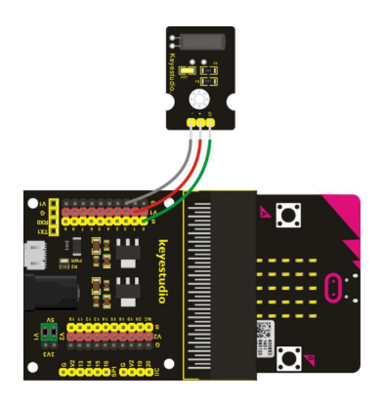
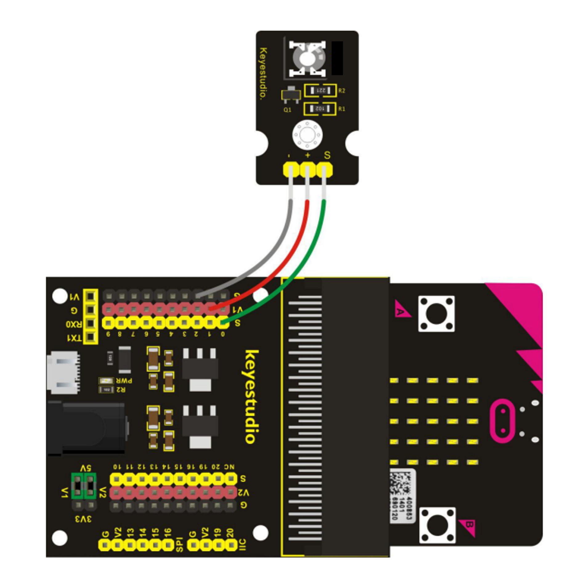
Wiring
Component 2
Wiring
Component 3
Wiring
Component 4
Wiring
Component 5
Wiring
Component 6
Wiring
Component 7
Wiring
Component 8
Wiring

Component 9
Wiring
Component 10
Wiring
Component 11
Wiring
Component 12
Wiring
Component 13
Wiring
Component 14
Wiring
Component 15
Wiring
Component 16
Wiring
Component 17
Wiring
Component 18
Wiring
Component 19
Wiring
Component 20
Wiring
Component 21
Wiring
Component 22
Wiring
Component 23
Wiring
Component 24
Wiring
Programming
This component is an INPUT device.
To use this in a program, you will need to determine if it is analog(ue) or digital.
How do we do that?
We shall initially treat all inputs as analog(ue) - we will then see all values received. If there are only two values we know the device is digital.
Programming
This component is an OUTPUT device.
To use this in a program, you will need to determine if it is analog(ue) or digital.
How do we do that?
We shall need to try both of the below programs to determine the output type of this component,
Please note: It is possible for an output to be both analog(ue) and digital - allowing us to choose how to program it.
Please note: This device has three different inputs to investigate.
Please note: This device has three different outputs to investigate
The test program:
In Makecode, reproduce the below program.
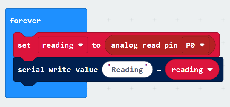
- The forever block should be there on loading a new project, otherwise it can be found in the Basic menu.
- The set "" to "" block can be found in the Variables menu.
- In the Variables menu you will also need to create a new variable called reading.
- The analog read pin block is found in the Pins menu - you will need to look in the Advanced drop-down for this.
- The serial blocks can be found in the Serial menu - also found in the Advanced menu.
The test program:
In Makecode, reproduce the below program.
You will also need to add a new menu of blocks. To do this, select Extensions from the menu and select the one called Sonar.
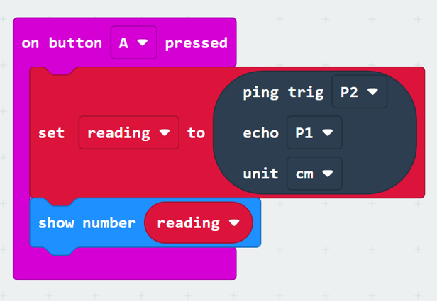
- The on button A pressed block can be found in the Input menu.
- The set "" to "" block can be found in the Variables menu.
- In the Variables menu you will also need to create a new variable called reading.
- The ping/echo/unit block is in our newly added Sonar menu.
- Use the drop down options to select the correct values for ping, echo, and unit.
- The show number block can be found in the Basic menu.
The Test Program
In Makecode, reproduce the below program.
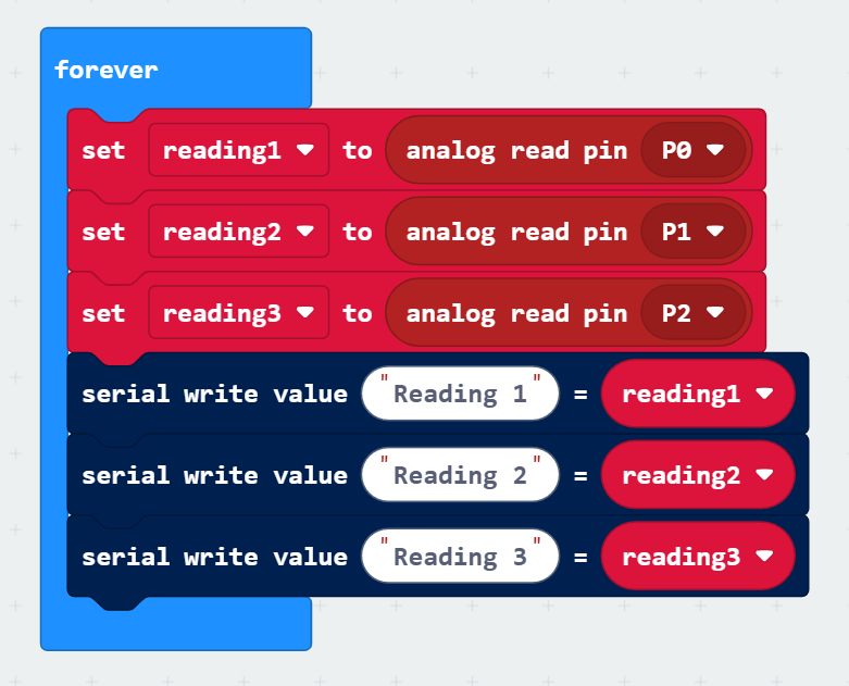
- The forever block should be there on loading a new project, otherwise it can be found in the Basic menu.
- The set "" to "" block can be found in the Variables menu.
- In the Variables menu you will also need to create new variables called reading1, reading2, and reading3.
- The analog read pin block is found in the Pins menu - you will need to look in the Advanced drop-down for this.
- The serial blocks can be found in the Serial menu - also found in the Advanced menu.
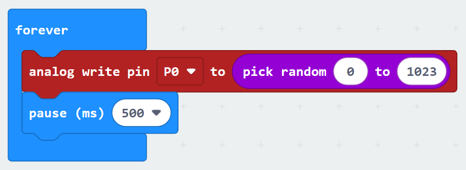
- The forever and pause blocks are both available in the Basic menu.
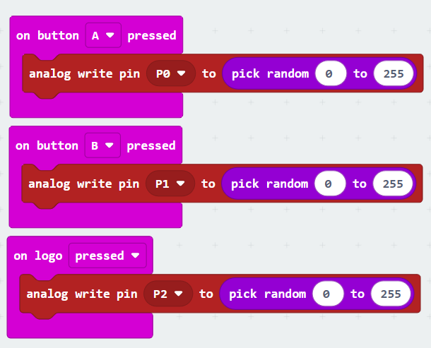
- The analog write pin block can be found in the Pins menu - found in the Advanced drop-down list
- The pick random block is in the Maths menu.
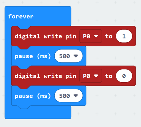
- The forever and pause blocks are both available in the Basic menu.
- The digital write pin blocks can be found in the Pins menu - found in the Advanced drop-down list
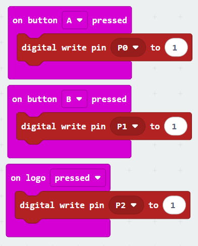
- The on button and on logo blocks can be found in the Input menu.
- The digital write pin blocks are available in the Pins menu which can be found in the Advanced drop-down.
- The on button and on logo blocks can be found in the Input menu.
- The analog write pin blocks are available in the Pins menu which can be found in the Advanced drop-down.
- The pick random inserts can be found in the Maths menu.
Running the tests
You can now download the program to your Micro:Bit.
This component does not require additional power so you do not need to connect the battery bank.
Leave the Micro:Bit connected to the computer and select the Show data Device button beneath the simulator.
This will show a graph of the input values received. Is it analog(ue) or digital?
Can you work out what the component is measuring? There is a component list button at the bottom of this page that may help.
Running the tests
You can now download the program to your Micro:Bit.
This component does not require additional power so you do not need to connect the battery bank.
To stop the program (some outputs can be annoying), unplug from the computer.
Running the tests
You can now download the program to your Micro:Bit.
Unplug the Micro:Bit from your computer.
Connect the provided power bank to the breakout board, connecting it to the Micro:Bit will limit the power available.
To stop the program (some outputs can be annoying), unplug the power bank.
Running the tests
You can now download the program to your Micro:Bit.
Unplug the Micro:Bit from your computer.
Connect the provided power bank to the breakout board, connecting it to the Micro:Bit will limit the power available.
This test program will print the reading on the Micro:Bit's screen everytime you press button A on it. Are the numbers showing this to be an analog(ue) or a digital device?
Can you work out what the component is measuring? There is a component list button at the bottom of this page that may help.
WARNING: Do not operate using additional power as it can make the output damaging/unsafe!
All Input Components
- Magnetic Sensor: Detects the north pole of a magnet (the red end). Easily mistaken for a Reed sensor
- Touch Sensor: Detects being touched - works well with skin contact due to its conductive properties. Not to be confused with the pressure sensor and/or the steam/humidity sensor.
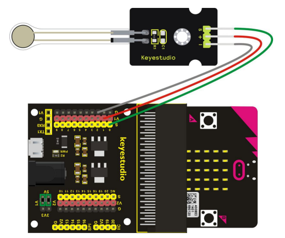
- Pressure Sensor: Measures how hard the sensor is being pressed. Please be careful not to over-do this test as components have a low stress limit. Not to be confused with the touch sensor and/or the steam/humidity sensor.
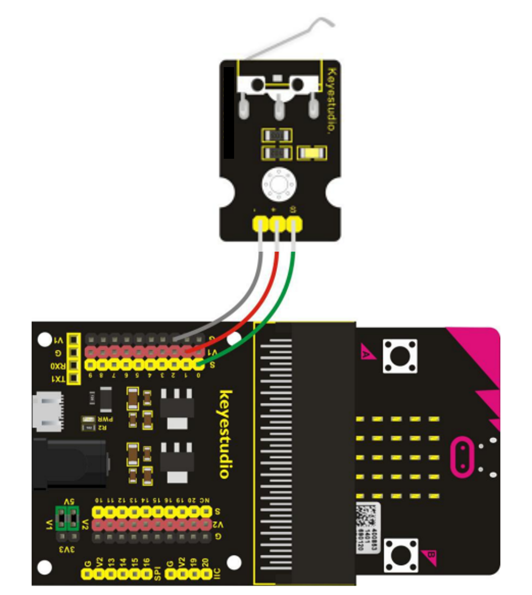
- Bumper Sensor: Used to detect if the sensor has 'bumped' into an object. Often mistaken as a generic push-switch.
- Tilt Sensor: Detects tilt in any direction.
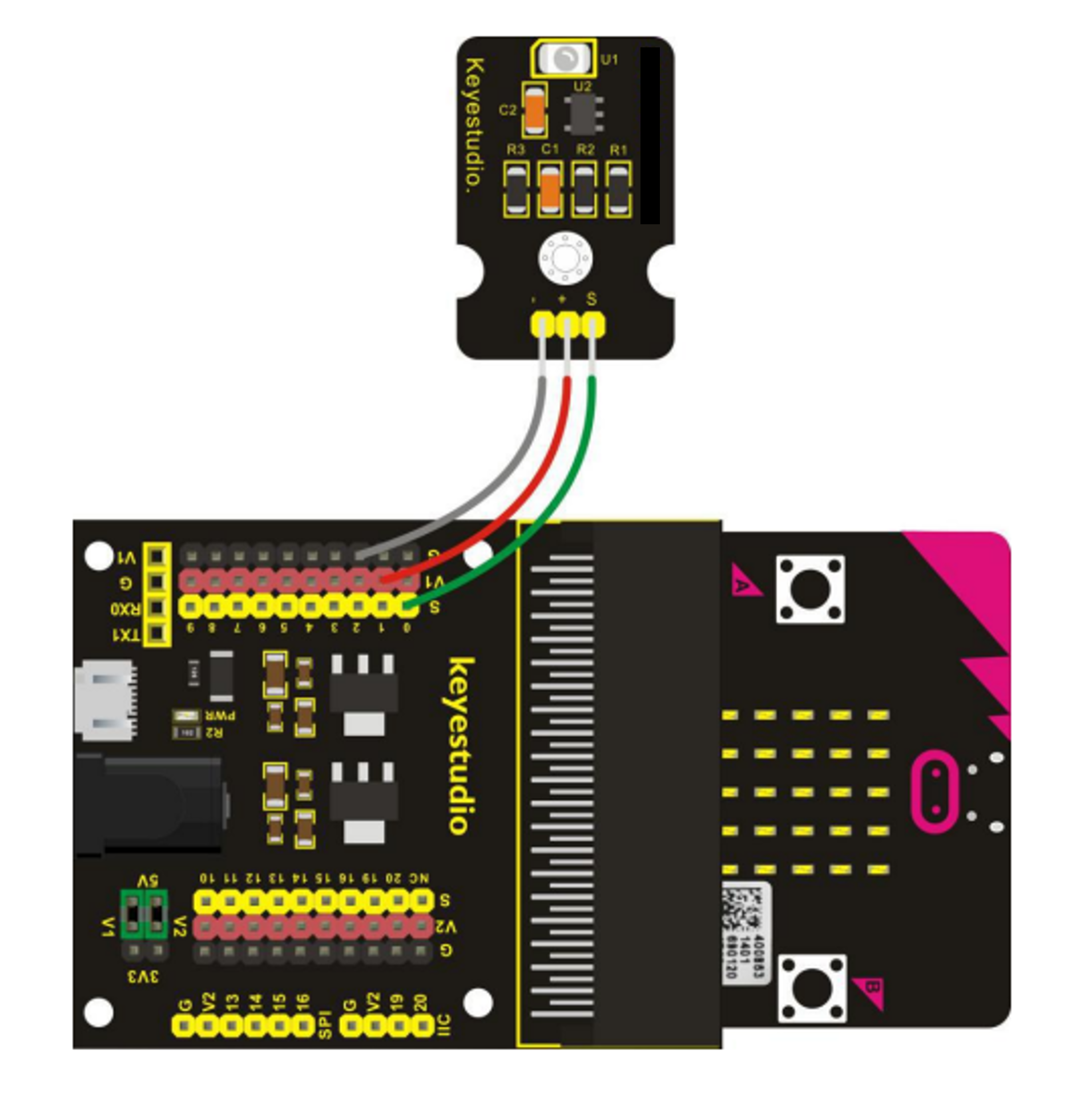
- UV Light Sensor: Measures the level of UV light present. Can be hard to distinguish from the generic light sensor, depending on light source used. There are low-powered UV torches provided for testing.
WARNING: Never shine UV light sources into anyone's eyes or on their skin. - Shake Sensor: Detects if it is being shaken. Easily confused with the tilt sensor.
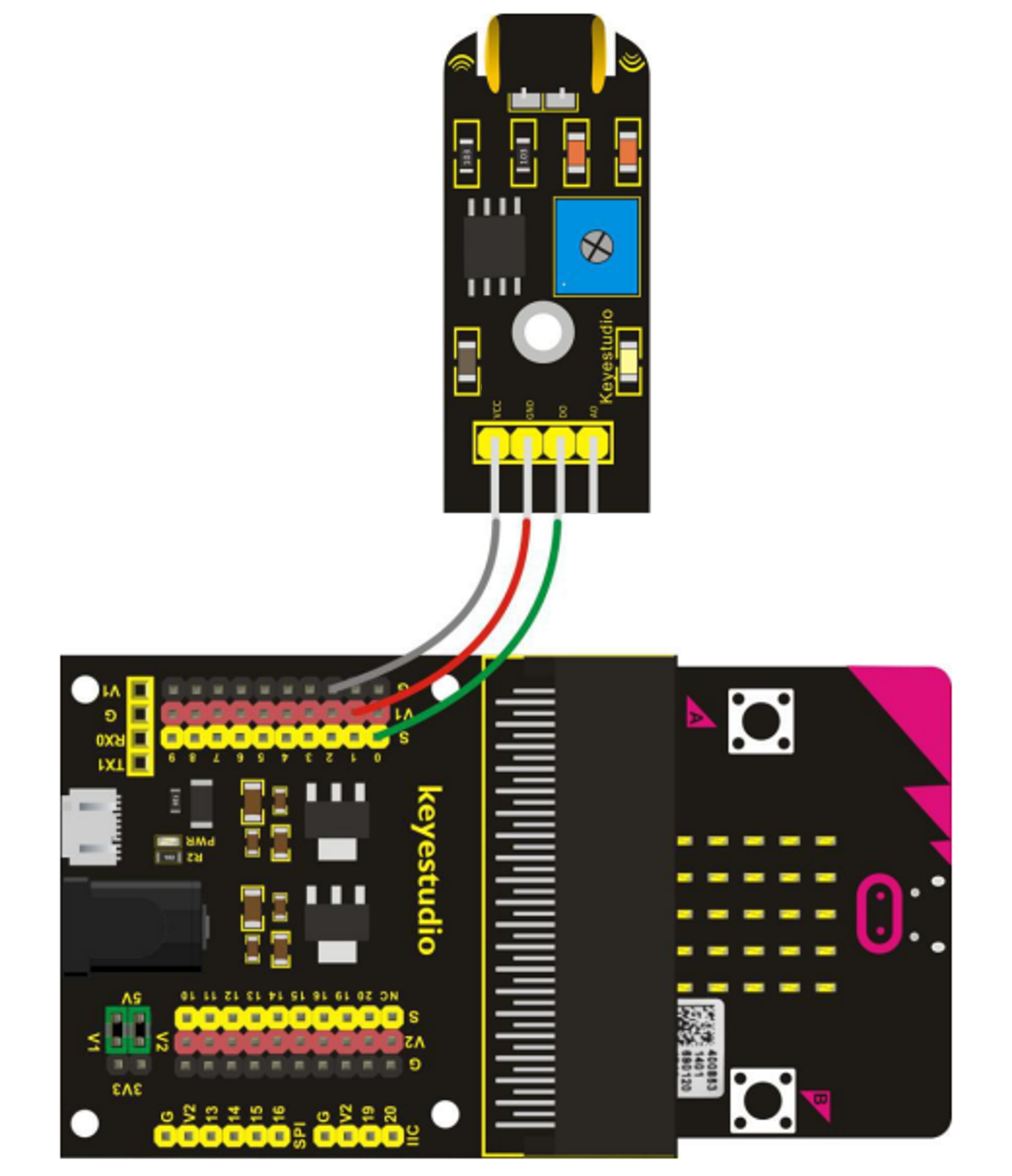
- IR (Infra-Red) Sensor: This sensor detects a nearby object/obstacle.
- Reed Sensor: This is the official name of a magnetic switch which detects a magnetic field. Often confused with the magnetic sensor.
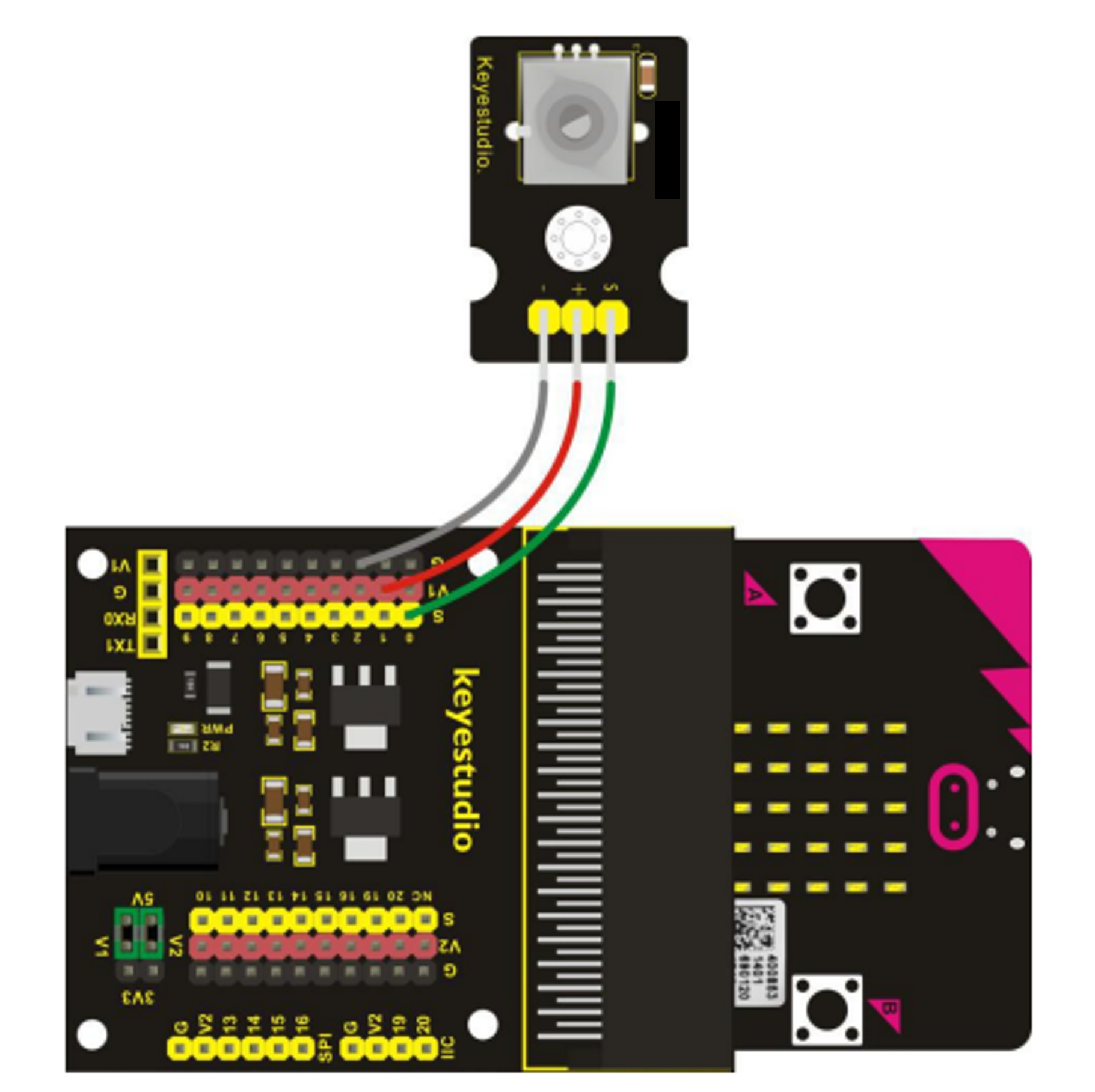
- Rotational Switch: Measures the position of the dial and its rotation.
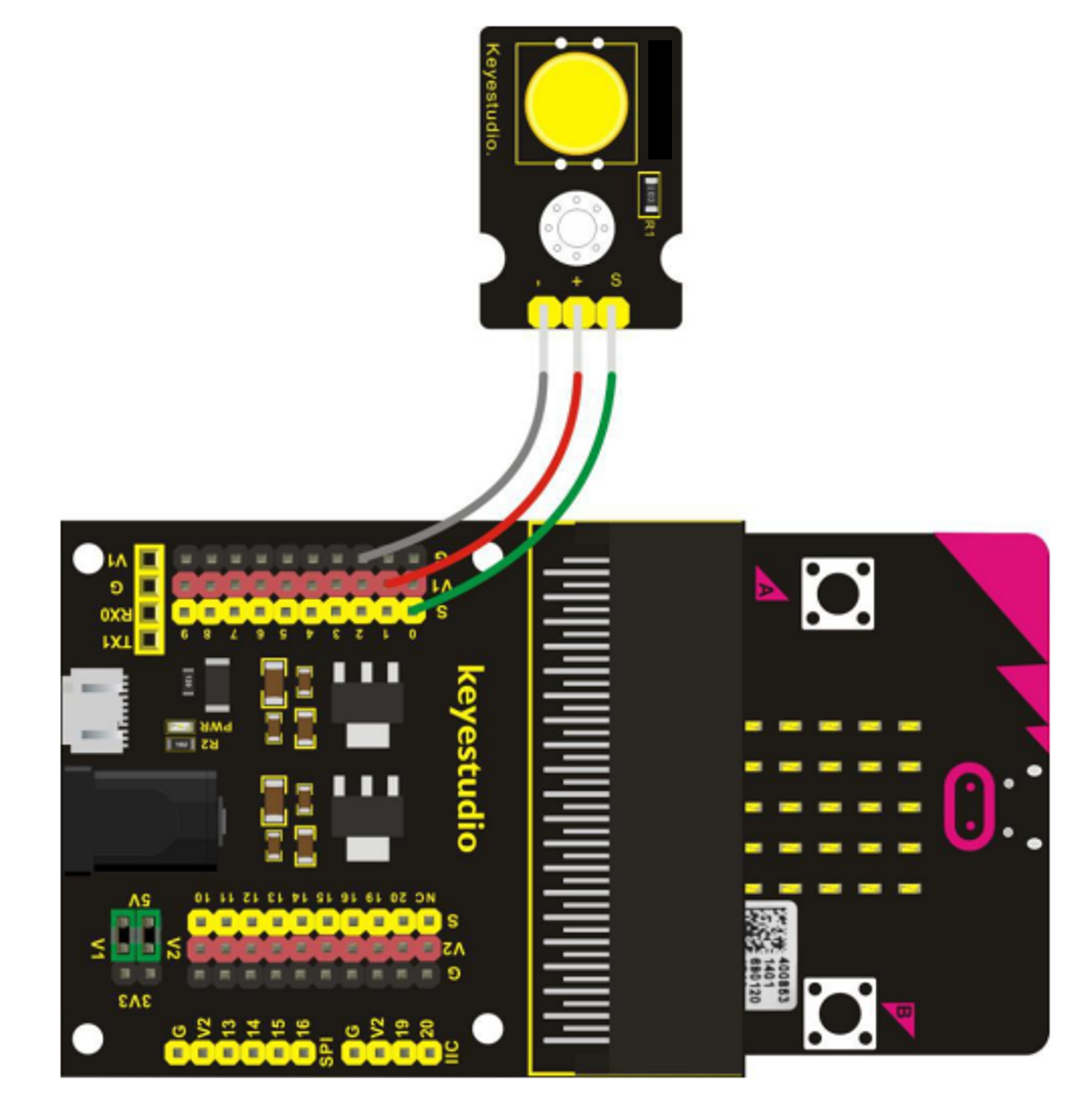
- Button: Can detect when pressed.
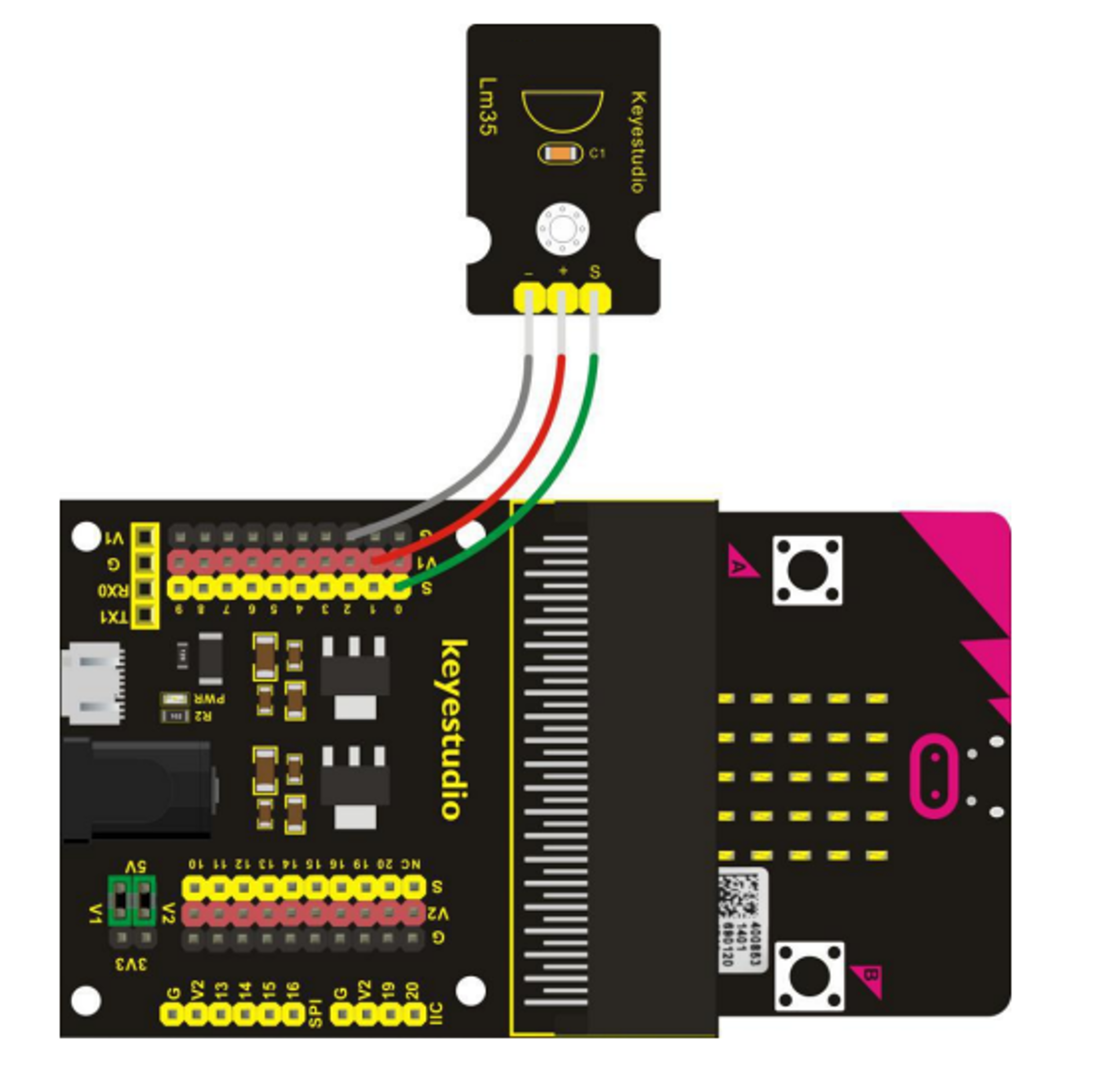
- Temperature Sensor: Measures the temperature. The best test is to slowly warm it a soft grip of your hands.
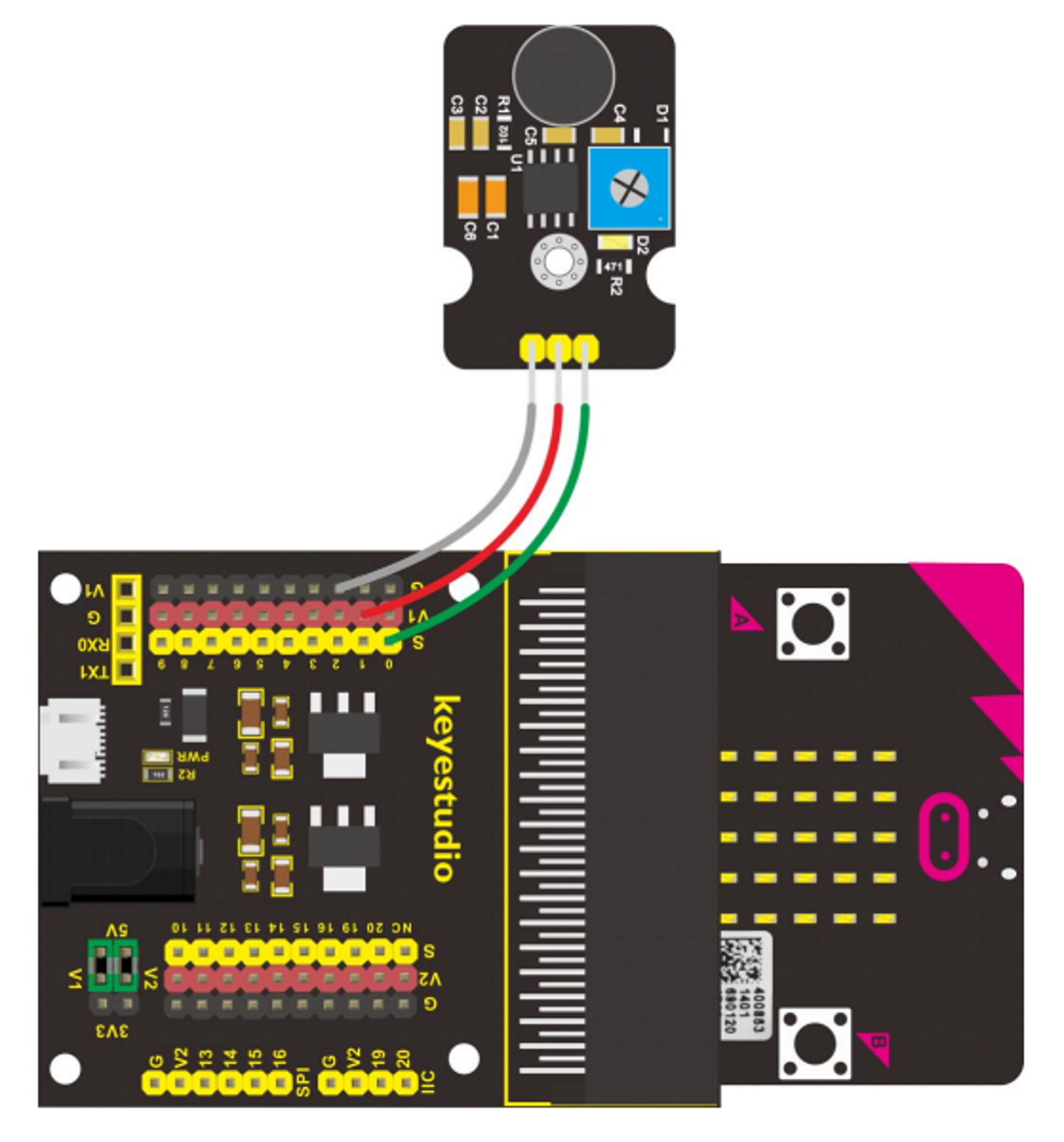
- Sound Sensor: Measures sound levels. Hard to test for in noisy environments.
- Light Sensor: Measures light level. Easily confused with the UV light sensor as some light sources contain both.
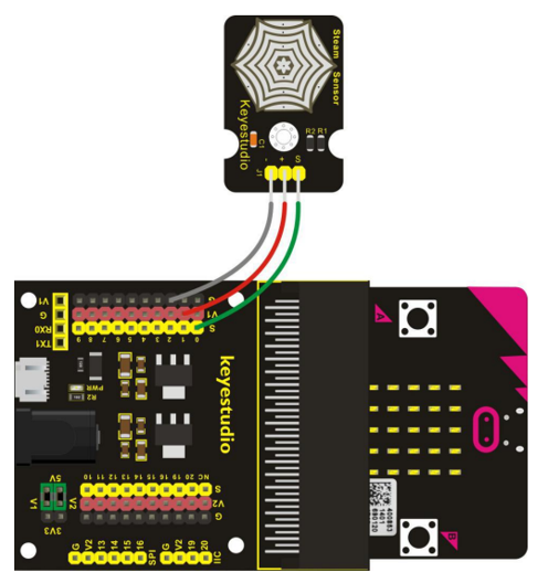
- Steam/Humidity Sensor: Measures water content of the air. We can trick the sensor to give a reading by putting a fingeer on it as the water content of our skin is higher than that of the air. However, makes it easy to confudse with the touch sensor and/or pressure sensor.
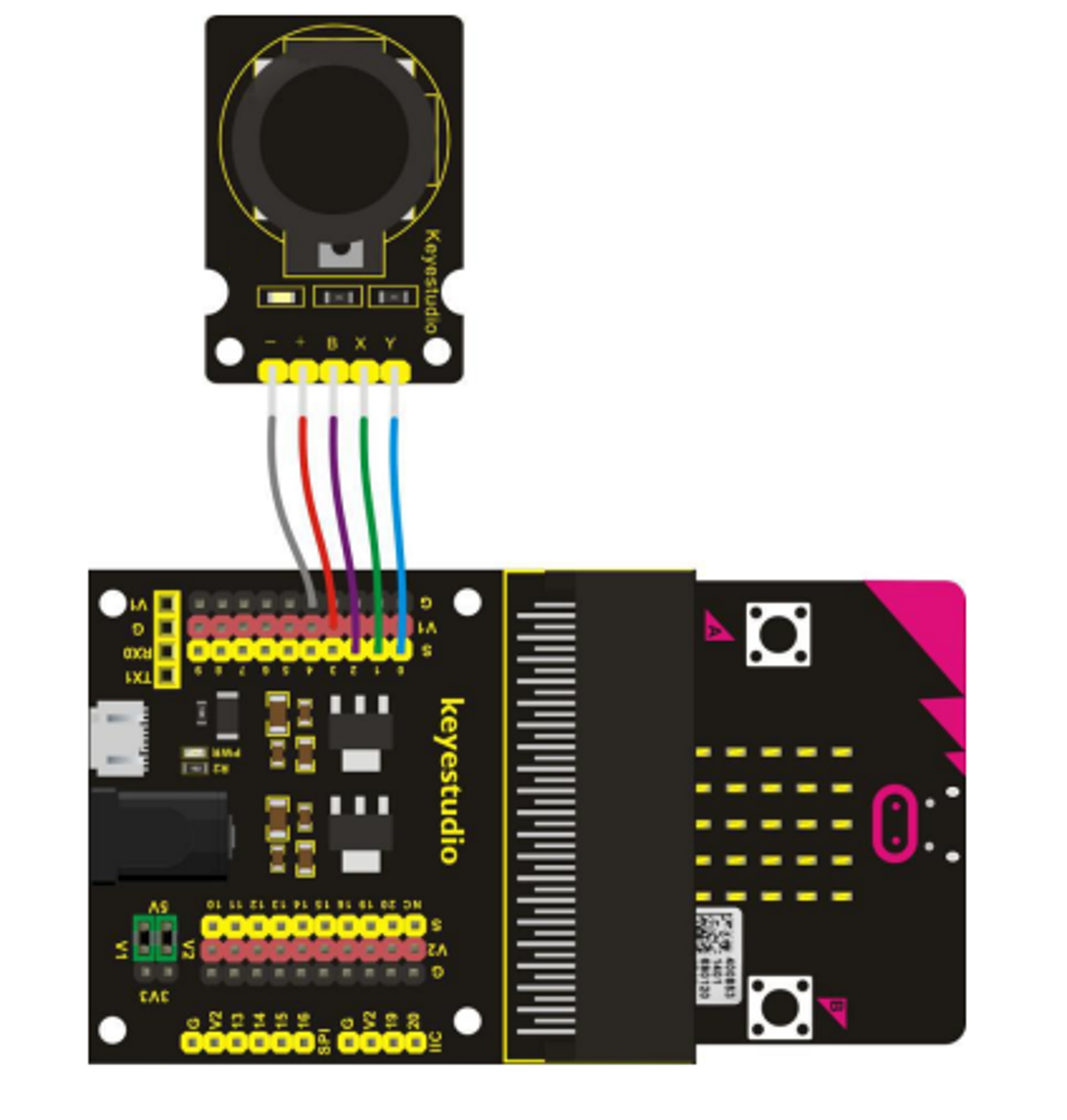
- Joystick: Measures direction of the joystick's movement and pressure when used as a button.
- PIR (Passive Infra-Red) Sensor: Detects movement. Be aware, this component is slow to respond to being moved.
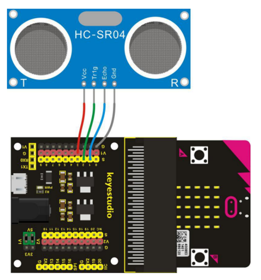
- Ultrasonic Sensor: Uses sound to measure distance to obstacles - similar to echolocation used by bats.
All Output Components
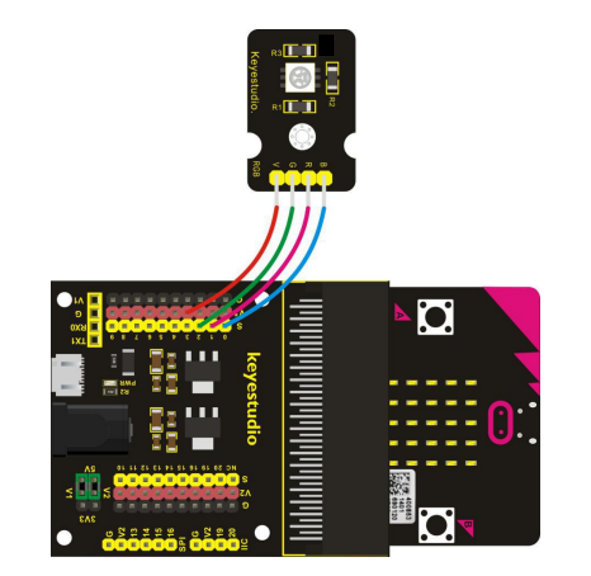
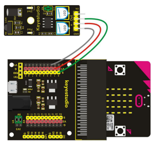
- RGB LED: A light which can produce a range of different colours using 3 inputs.
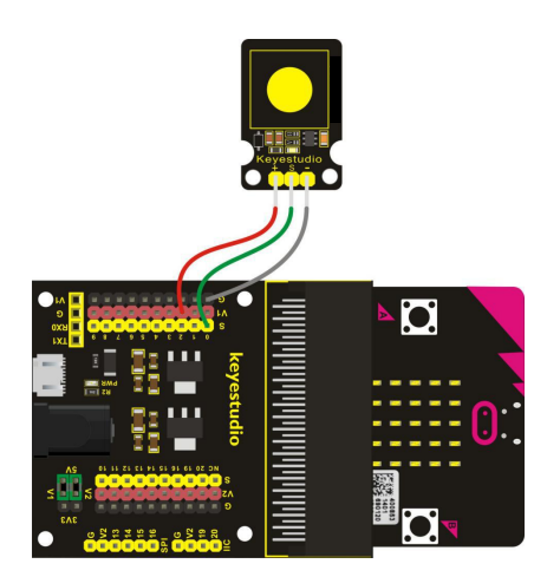
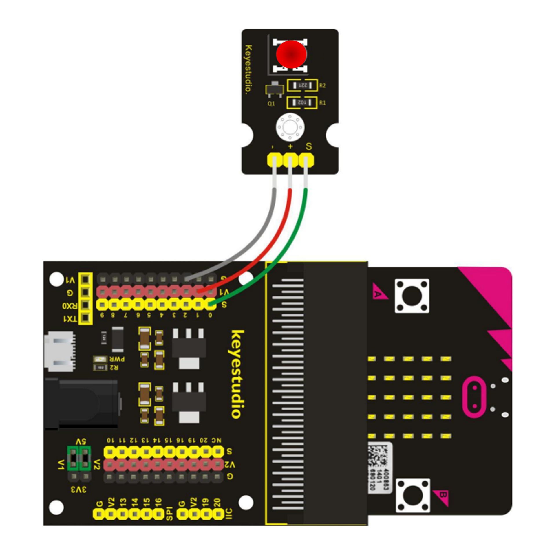
- Red LED: Produces only red light.
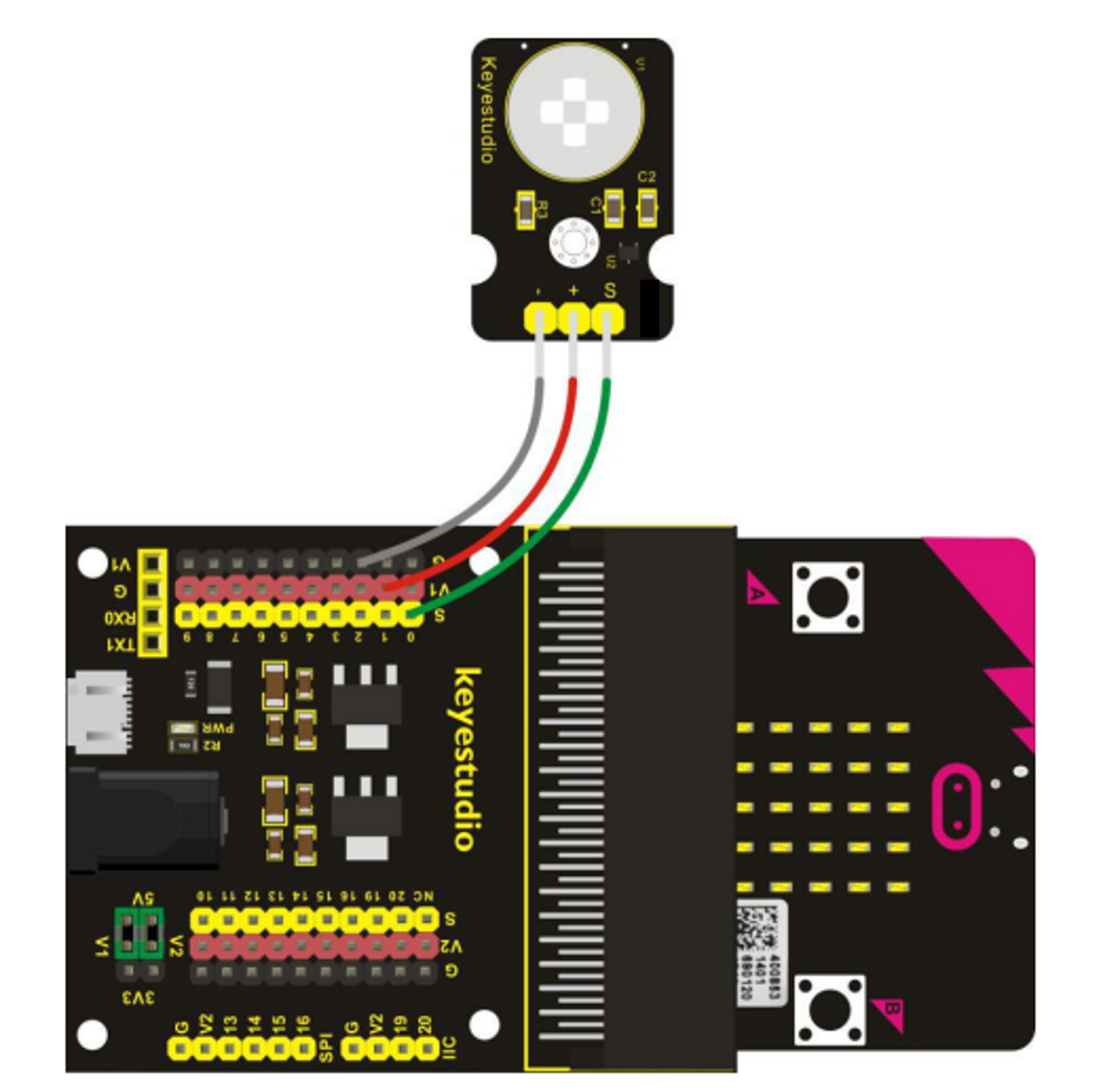
- Buzzer: Can produce a range of different tones. Please be considerate as this device can be very annoying, especially to those with audible sensitivities.
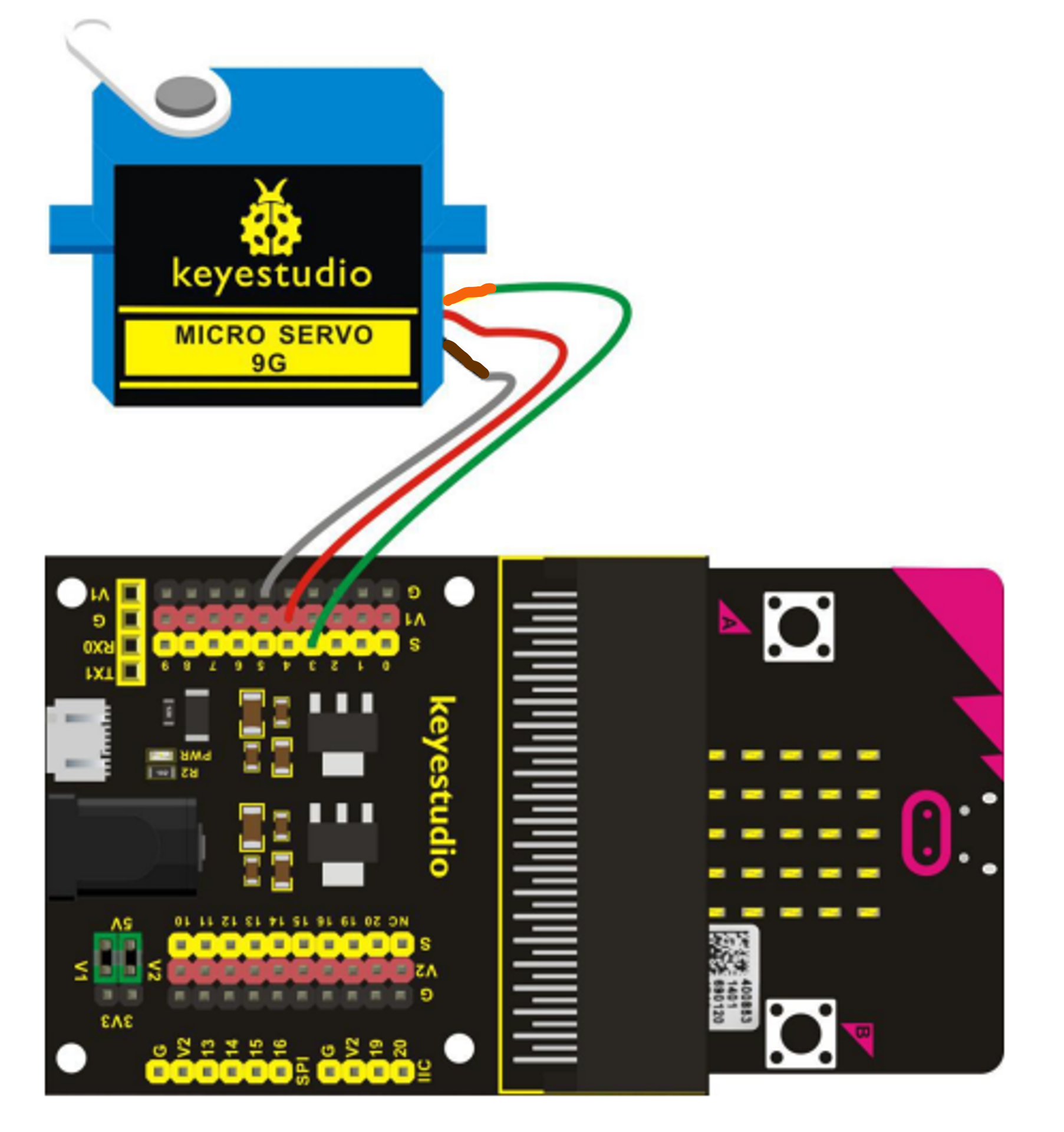
- Servo: Can rotate to a set point within a range of 180°
- White LED: Produces only white light.
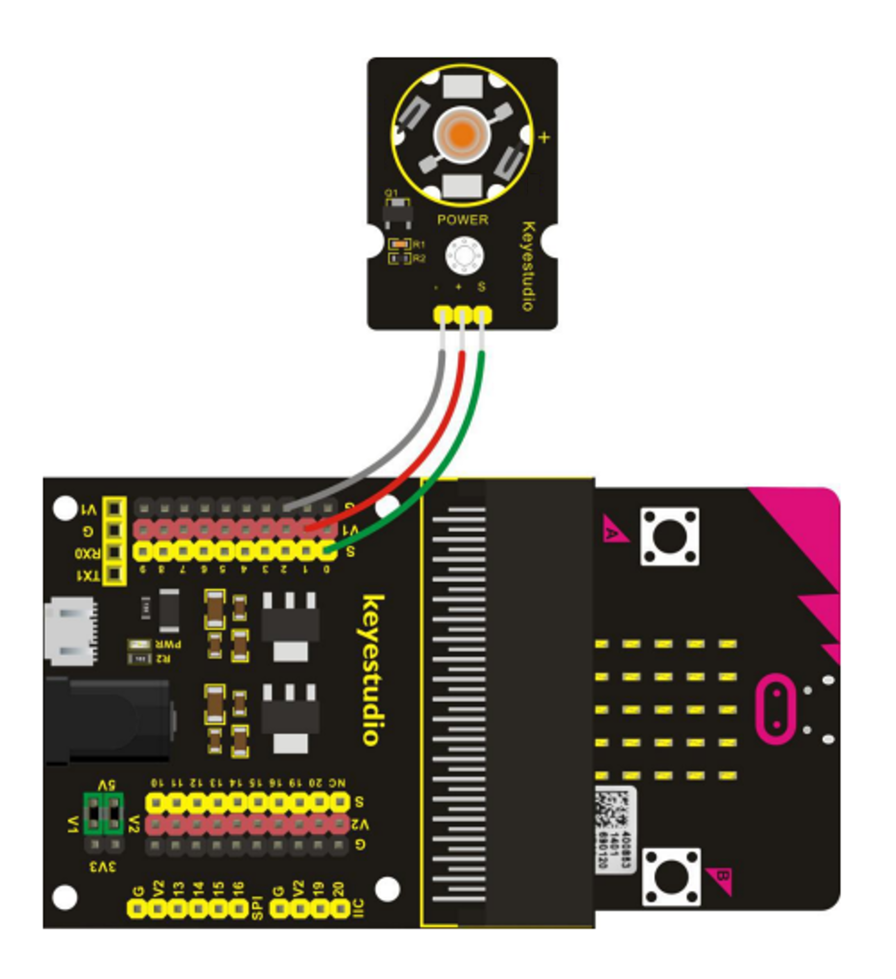
- Super Bright LED: Produces a brighter warm white light.
WARNING: Do not shine bright lights towards anyones' eyes, and be extra careful if using additional power source.
Connecting a Neopixel
Now that you've identified your input device and what it is measuring we shall connect an output called a Neopixel Strip to your circuit and program the lights to react to the input value.
For this program you will need to add the neopixel extension to Makecode.
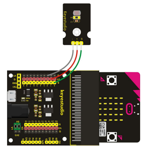
Wiring
Look at the labels on the back of the neopixel strip where the wires connect. They should be labelled as GND, DI, and VCC.
Connect the wire from the GND to any of the black pins on the breakout board.
Connect the VCC wire to any of the red pins on the breakout board.
The wire for DI needs to connect to yellow pin number 8.
Programming
Analog(ue) Inputs
Below is an example program for using the neopixel strip with an analog(ue) input device.
If you are using a device with more than one input pin you will need to adapt the program to read each one and give a different response.
- The on start and forever blocks are found in the Basic menu.
- All blocks referring to 'strip' are found in the Neopixel menu (as long as you added the neopixel extension).
- The set reading block is found in the variable menu (if not already available create a new variable called 'reading').
- The analog read block is in the Pins menu found in the Advanced drop-down section.
- The if/else block is found in the Logic menu along with the > insert block.
This program may need adjustments to match the values to the range detectable and controllable within the environment. For example, if the class is noisy, the sound sensor will need a higher value to activate the output or else we cannot test if it turns off.
Digital Inputs
Below is an example program for using the neopixel strip with an digital input device.
- The on start and forever blocks are found in the Basic menu.
- All blocks referring to 'strip' are found in the Neopixel menu (as long as you added the neopixel extension).
- The set reading block is found in the variable menu (if not already available create a new variable called 'reading').
- The digital read block is in the Pins menu found in the Advanced drop-down section.
- The if/else if/else block is found in the Logic menu along with the = insert block.
This program includes an error capture - this means if the input is not 0 or 1, the word 'ERROR' will scroll across the Micro:Bit screen. This means that either there is an error in your program and/or the input you're using is analog(ue) not digital.
Testing
Download the program to your Micro:Bit.
Unplug from the computer.
Connect a battery pack/power bank to the breakout board (not the Micro:Bit). We need to provide extra voltage to support the use of two components.
Check that the program behaves as expected. If not, check your code and/or make modifications to values and start the testing process again.
WARNING: The neopixel strips can be very bright and cause dazzling. If it is too bright to work with, there is a 'strip set brightness' block in the Neopixel more menu which you can use to reduce it (255 is the maximum value with 0 as off).
Extensions
For Analog(ue) Inputs
You can add else if statements to your program (just click on the plus symbol within the 'else' section of the if/else block) to have different lighting affects to represent different levels of readings.
If you're feeling particularly confident/brave you could have a look at mapping the value of the input onto the output. This means that the lighting on the neopixel would be indicative of the strength of the input. The higher the input value, the more lights show.
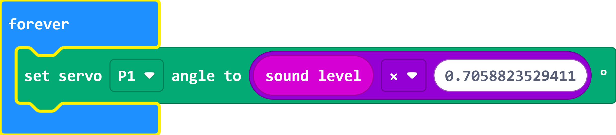
We've put together an example of using mapping with the input of sound using a sensor with a range of 0 (silent) to 255 (very loud) onto a servo which can rotate between 0° and 180°. This recreates a dial effect where a needle connected to the servo would indicate the noise level.
Important: We have a range of 0° to 180° on the servo but the sound level has a range of 0 to 255. There are two ways to approach this:
Do the maths ourselves
-
Work out how far the meter needs to move for one unit of sound:
(180 ÷ 255) = 0.7058823529411°
-
Use the above value with a Maths block inside a 'set servo' block.
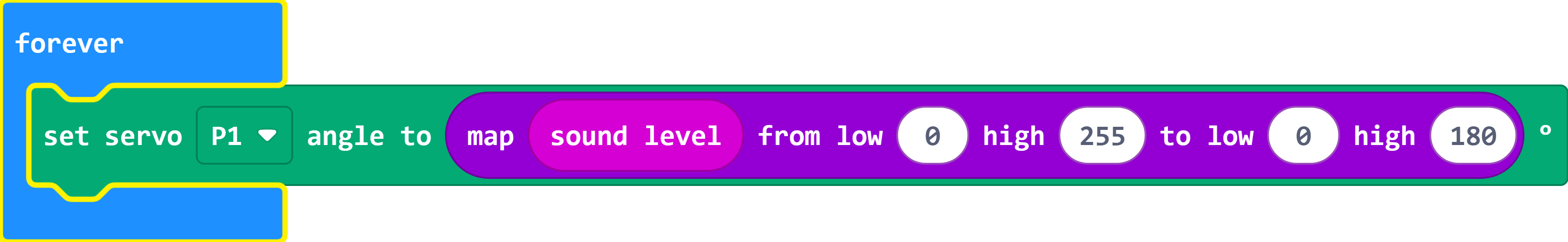
Use the 'map' block
-
The map block allows us to enter the range we're measuring (sound level) which is 0 to 255 and convert it to the servo's range of 0 to 180. The block then does all the calculations for us.
For more background and information feel free to review the exercises in Session Five of our Micro:Bit Programming Series.
For Digital Inputs
If your input was a digital device, you have more limitations on options for an output, it's either on or off.
However, that does not mean you cannot have fun exploring ways to create a unique colour effect and/or a randomised output when activated.
One way to do this would be to program each LED of the strip individually and set the colour value of each independently. To do this you will need to use the 'range' blocks available in the Neopixel menu.
Check out the exercises for Session Four of our online Micro:Bit series for more information about programming different parts of a neopixel strip.
Done?
If you've finished your circuit and are happy that it works how you want, feel free to start again with a different numbered component.
Connecting an Ultrasonic Sensor
Now that you've identified your output device and whether it's digital or analog(ue) we shall connect an input called an ultrasonic sensor to your circuit and program your output to react to it.
For this program you will need to add the sonar extension to Makecode.
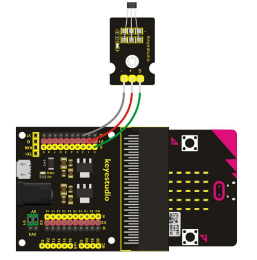
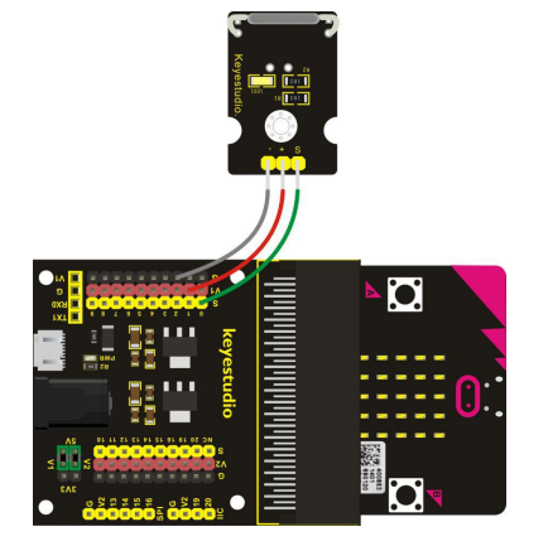
Wiring
This new component has four connection points
- Connect the VCC pin to any of the red pins on the left of the breakout board.
- Connect the GND pin to any of the black pins on the left of the breakout board.
- Connect the trig pin to yellow pin number 7.
- Connect the echo pin to yellow pin number 8.
Programming
The input we're receiving from the ultrasonic can be set to centimetres (however, the accuracy is not very good). We can then design a program that either outputs when an object gets too close or have an output that indicates difference.
For Analog(ue) Outputs
Below is an example/starter program for use with an analog(ue) output device.
If you are using a device with more than one output pin you will need to adapt the program to write to each one.
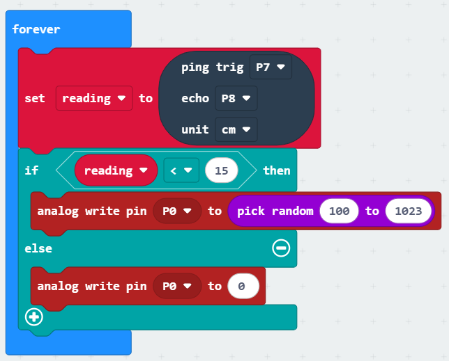
- If you have removed or lost the forever block, you can find it in the Basic menu.
- The set reading block is from the Variables menu where you will need to create a new variable called 'reading'.
- The ping, echo, and unit block is found in the Sonar menu (made available after adding the Sonar extension).
- The if block is from the Logic menu along with the < insert.
- The analog write blocks are from the Pins menu within the Advanced drop-down.
- The pick random block can be found in the Maths Menu.
For Digital Outputs
Below is an example/starter program for use with a digital output device.
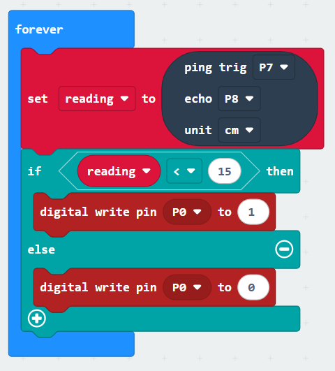
- If you have removed or lost the forever block, you can find it in the Basic menu.
- The set reading block is from the Variables menu where you will need to create a new variable called 'reading'.
- The ping, echo, and unit block is found in the Sonar menu (made available after adding the Sonar extension).
- The if block is from the Logic menu along with the < insert.
- The digital write blocks are from the Pins menu within the Advanced drop-down.
Testing
- Download your program to the Micro:Bit.
- Unplug from the computer.
- Connect a battery pack/power bank to the breakout board (not the Micro:Bit).
WARNING! If using the Super Bright LED, this increased power will make it even more blinding. Make sure you have it safely shielded so as not to cause eye damage to anyone in the room.
Extensions
For Analog(ue) Outputs
You can add else if statements to your program (just click on the plus symbol within the 'else' section of the if/else block) to have different outputs to represent different distances.
If you're feeling particularly confident/brave you could have a look at mapping the value of the input onto the output. This means that the output would be indicative of the closeness of an object.
We've put together an example of using mapping with the input of sound using a sensor with a range of 0 (silent) to 255 (very loud) onto a servo which can rotate between 0° and 180°. This recreates a dial effect where a needle connected to the servo would indicate the noise level.
Important: We have a range of 0° to 180° on the servo but the sound level has a range of 0 to 255. There are two ways to approach this:
Do the maths ourselves
-
Work out how far the meter needs to move for one unit of sound:
(180 ÷ 255) = 0.7058823529411°
-
Use the above value with a Maths block inside a 'set servo' block.
Use the 'map' block
-
The map block allows us to enter the range we're measuring (sound level) which is 0 to 255 and convert it to the servo's range of 0 to 180. The block then does all the calculations for us.
For more background and information feel free to review the exercises in Session Five of our Micro:Bit Programming Series.
For Digital Outputs
There are less options for varying the result of your circuit when using a digital output.
One suggestion would be to test the accuracy of the ultrasonic sensor by changing the value that triggers your output and comparing it to the actual measurement that triggers it in testing.
Done?
If you've finished your circuit and are happy that it works how you want, feel free to start again with a different numbered component.