Introduction to Electronics
These resources have been developed to support our in-person workshop.
Exercise One: LEDs
-
Create a new project on Makecode.
-
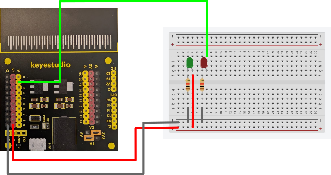
Program your Micro:Bit to make the red LED in the below circuit flash on and off.
Programming tip: You will find the digital write blocks needed in the Pins menu (inside the Advanced drop-down menu)
on start show string "Aber" forever digital write pin P1 to 1 pause (ms) 500 digital write pin P1 to 0 pause (ms) 500 -
Create this circuit using the electronics provided to test your program.
Programming tip: Your program must have a pause after turning on and after turning off the LED. You can change the pause length if you want to make the LED flash faster or slower.
Exercise Two: Ultrasonic
The ultrasonic sensor has four connection points and requires additional set-up. You will need the extension for sonar to include a specialist block in your menu.
-
Create a variable in your program called "ultrasonic" and set it to 0 in the on start block.
To keep taking fresh readings from the ultrasonic you will need to set this new variable to the sonar reading (in cm) inside the forever block. Check the wiring image below to ensure you set the trig and echo pins correctly.
Programming tip: Variables should always start with a lower-case letter and not include spaces. Variables should always be declared in the set-up (on start block).
on start set ultrasonic to 0 show string "Aber" forever set ultrasonic to ping trig P10 echo P11 unit cm digital write pin P1 to 1 pause (ms) 500 digital write pin P1 to 0 pause (ms) 500 -
Change your code to have the red light only come on when something is detected 5cm or less from the sensor.
Programming Tip: Best way to do this is with an if and an else statement, the if will let you set the distance for turning the light on, whilst the else can be used to turn it off again.
on start set ultrasonic to 0 show string "Aber" forever set ultrasonic to ping trig P10 echo P11 unit cm if ultrasonic ≤ 5 then digital write pin P1 to 1 pause (ms) 500 else digital write pin P1 to 0 pause (ms) 500 -
Add the ultrasonic sensor to your circuit as shown:
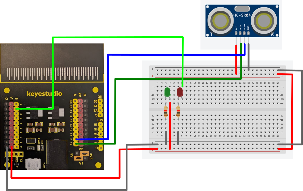
Wiring Tip: Notice how the ultrasonic sensor is not on the board but connected to it.
Now you can test your program.
Exercise Three: Inputs
-
For this exercise we shall be adding a light dependent resitor (LDR) to your circuit.
This component allows us to measure the light level and have our circuit react to different brightnesses detected.
Update your cicuit to match this wiring diagram:
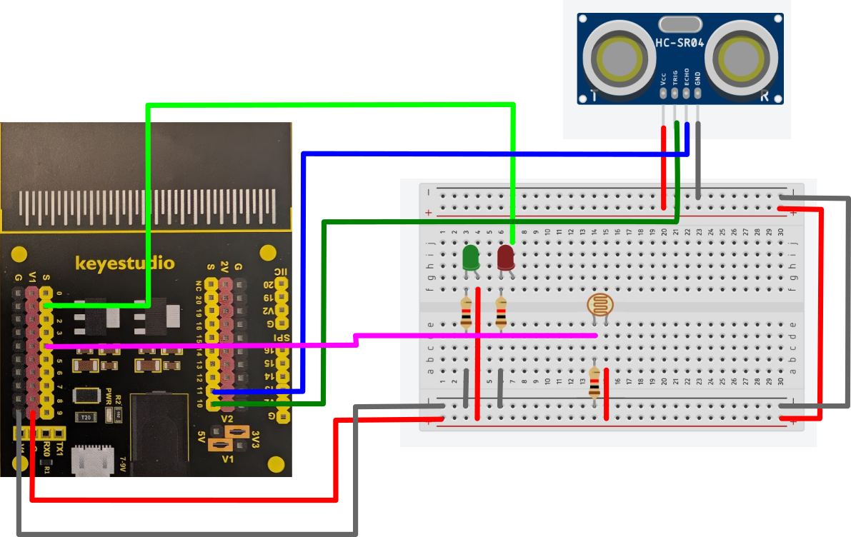
Wiring Tip: Notice how we use a resistor in place of a wire for bridging a gap on a breadboard.
Add an instruction to your program to show the input values on the Makecode serial monitor.
Programming Tip: You will need to create a new variable to store the input value of the LDR.
on start
  set ultrasonic to 0
  set ldr to 0
  show string "Aber"

forever
    set ultrasonic to ping trig P10
                      echo P11
                      unit cm
    set ldr to analog read pin P4
    if ultrasonic ≤ 5 then
      digital write pin P1 to 1
      pause (ms) 500
    else
      digital write pin P1 to 0
      pause (ms) 500
    serial write value "lightLevel" = ldr
    pause (ms) 500
To test this, you will need to leave the Micro:Bit plugged into your computer and access the serial monitor for the device. This will allow you to see the range of values being measured.
-
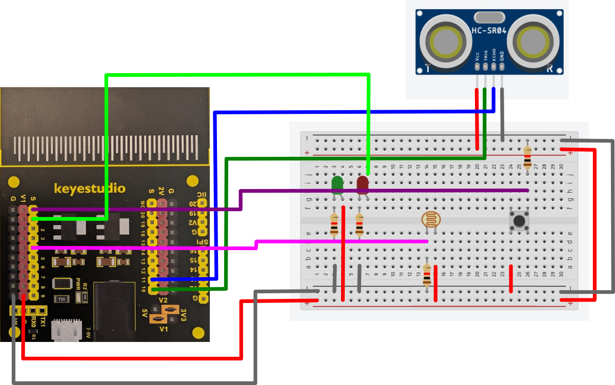
Let us now add a button to our circuit as shown in the below diagram.
-
A new variable called 'button' will be needed to read the digital input from the button. the value of 1 means the button is being pressed, 0 means it is not.
on start set ultrasonic to 0 set ldr to 0 set button to 0 show string "Aber" forever set ultrasonic to ping trig P10 echo P11 unit cm set ldr to analog read pin P4 if ultrasonic ≤ 5 then digital write pin P1 to 1 pause (ms) 500 else digital write pin P1 to 0 pause (ms) 500 serial write value "lightLevel" = ldr pause (ms) 500 -
Add another new variable called 'power' to your program. Have this value change between on and off (1 and 0) whenever the button is pressed.
Programming Tip: You can put if-statements inside other if-statements - we call this stacking.
on start set ultrasonic to 0 set ldr to 0 set button to 0 set power to 0 show string "Aber" forever set ultrasonic to ping trig P10 echo P11 unit cm if ultrasonic ≤ 5 then digital write pin P1 to 1 else digital write pin P1 to 0 set button to digital read pin P0 serial write value "lightLevel" = ldr pause (ms) 500 if button = 1 then if power = 0 set power to 1 else set power to 0 -
For the last part of this exercise, you now need to get the reading from the LDR to show on the screen when the button is pressed.
Move the set ldr to analog input block into this new if-statement to make sure the reading is true to when the button is pressed and not from a different stage in the program.
We no longer need the ldr value showing in the serial monitor, or the pause connected to that instruction.
Programming Tip: You will need to reset the power variable to 0 after showing the LDR value to allow a single reading.
  on start
    set ultrasonic to 0
    set ldr to 0
    set button to 0
    set power to 0
    show string "Aber"

  forever
    set ultrasonic to ping trig P10
                      echo P11
                      unit cm
    if ultrasonic ≤ 5 then
      digital write pin P1 to 1
    else
      digital write pin P1 to 0
    set button to digital read pin P0
    if button = 1 then
      if power = 0
        set power to 1
      else
        set power to 0
    if power = 1 then
      set ldr to anolog read pin P4
      show number LDR
      set power to 0
Exercise Four: Smart Home System
This exercise looks at modelling some practical applications to the circuit you've created.
Start a new program for this. Save the previous one for reference on code each of the components.
Our new program should do the following:
-
The red LED should only turn on when the LDR detects darkness.
Programming Tip: Testing this with the serial monitor in exercise three, should have provided you with a suitable value to use.
-
The button should activate/deactivate an alarm system which is shown as on or off using relevant images on the Micro:Bit's screen.
-
The Micro:Bit has a speaker we can use as the alarm when the Ultrasonic detects an object in front of it (for testing purposes use 5cm for the alarm range).
Programming Tip: Please be aware of the annoyance alarm noises can cause to others, so keep it to a simple, short alert that lets you know the program works.
Extension: NeoPixels
This involves creating a new circuit, so please do not attempt until you've completed and successfully programmed the workshop's 'smart home' system.
-
Create the circuit below.
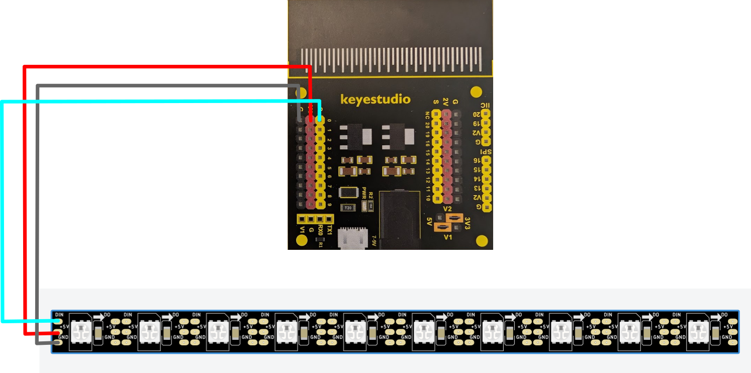
Wiring Tip: Quite often the connections on the components are arranged in a different order to diagrams. This is one example. Make sure that you check the back of the NeoPixel strip to ensure it's wired correctly. GND goes to the the G pin, VCC goes to the V1 pin, whilst the DIN goes to pin 0.
-
To program this in Makecode, you will need to add the neopixel extension.
In this new set of programming blocks you have some default variables for the LED strip. A 'strip' refers to the strip of LEDS connected - you have to tell the program how many LEDs it has. A range refers to part of the strip.
Set the strip variable to pin 0 with 10 RGB LEDs in the on start block.
Tell the program to have the strip display a rainbow.
  on start
    set strip to NeoPixel at pin P0 with 10 leds as RGB (GRB format)

  forever
    strip show rainbow from 1 to 360
Test your circuit and program.
WARNING! These LEDs are very bright. Do not direct them towards eyes (yours or other peoples). They are dazzling.
-
Now try to program the LEDs on the strip to turn on one at a turn to make it seem like the light is travelling along the strip.
Programming Tip: You will need to create 10 range variables, one for each LED to achieve this.
-
Using everything we've looked at during these exercise, see if you can wire up an ultrasonic sensor alongside your neopixel strip. Then, write a program where the LED strip acts as an indicator for how close something is.
For more information and additional challenges in electronics - visit our online Electronics Series.